
If you’re building an FPV drone, one of the most critical steps is learning how to connect a 4 in 1 ESC to a flight controller properly.
The 4 in 1 ESC (Electronic Speed Controller) acts as the bridge between your motors and your flight controller. A clean and correct connection ensures:
- smooth throttle response
- stable flight performance
- reliable long-term durability
Mess it up, and you’re looking at desyncs, motor glitches—or worse, a fried flight controller.
In this guide, I’ll walk you through 4 in 1 ESC wiring step by step, based on real FPV build experience.
Importance of Properly Connecting ESC to Flight Controller
The connection between the 4 in 1 ESC and flight controller is the nervous system of your FPV drone. It dictates every twitch, tilt, and loop, translating your pilot commands into precise electrical signals that power the motors. Neglecting this connection is like flying blindfolded; you might take off, but a smooth, controlled flight? Not so much.
Here’s why a proper connecting ESC to flight controller connection is crucial:
- Safety First: A wobbly, unreliable connection can lead to erratic motor behavior, potentially causing crashes and damaging your drone or worse. Imagine a rogue motor sending your drone spiraling towards the ground!
- Performance Precision: A seamless connection ensures smooth, responsive flight. Every nuance of your control stick will be translated into precise motor adjustments.
- Beyond Wires: It’s not just about physical connections. The 4 in 1 ESC and flight controller communicate through complex software protocols. Improper settings or firmware mismatch can wreak havoc.
- Feature Access: Many 4 in 1 ESCs and flight controllers boast advanced features like telemetry and motor diagnostics. However, these are locked away without a secure connection between the two.
If wiring esc to flight controller is not properly made, it can lead to a variety of problems, including:
- Motors not spinning
- Motors spinning at incorrect speeds
- Motors spinning in the wrong direction
- Flight controller crashing

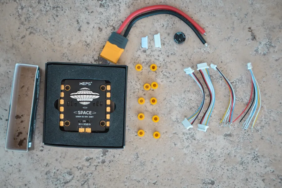
Understanding the 4-in-1 ESC
In an FPV drone, the motor speed is managed by an ESC, or electronic speed controller. The flight controller sends throttle signals to the ESC, which uses these to drive the brushless motor at the appropriate speed. A 4-in-1 ESC combines the control of four distinct motors from four separate ESCs onto a single circuit board.
4in1 ESCs may be installed quickly and easily because they are often the same size as the flight controller. They require less wiring and soldering since they have fewer solder joints. Usually mounted behind the flight controller, the 4in1 ESC is connected by a single wire harness. You will have to compromise between convenience and risk, though, as you will have to replace the entire board if one ESC is destroyed. But since 4in1 ESC are so dependable these days, there’s usually no need to worry. Furthermore, because of their centered bulk, 4-in-1 ESCs provide superior weight distribution, which can improve the drone’s response.
Based on mounting patterns for various drone sizes, three 4in1 ESC sizes are available:
- 30x30mm
- 20x20mm
- 16x16mm
Common 4 in 1 ESC Sizes:
| Size | Typical Use |
|---|---|
| 30x30mm | 5” freestyle / long-range |
| 20x20mm | 3–4” builds |
| 16x16mm | micro drones |
Larger ESCs usually have larger FETs, which translate into more power and durability. The most popular size for 5″ and larger FPV drones is 30x30mm.
👉 Explore the ESC and Flight Controller on MEPSKING.
Checking Compatibility between 4 in 1 ESC and Flight Controller
Before you grab the soldering iron, use this quick reference table to ensure your 4 in 1 ESC and flight controller are actually meant to work together.
| Feature | Requirement | Why it Matters |
| Mounting Pattern | 30.5×30.5mm, 20x20mm, or 25.5×25.5mm | Must fit your frame’s mounting holes. |
| Voltage Rating | 4S, 6S, or 8S compatibility | Plugging a 4S FC into an 8S ESC will result in immediate failure. |
| Amperage (Current) | Motor Max Amps + 20% margin | A 2207 1950KV motor on 6S needs at least a 50A-60A ESC. |
| Protocol Support | DShot300 / DShot600 / DShot2400 | Ensures the FC can “talk” to the ESC at high speeds. |
Voltage
The 4 in 1 esc and flight controller must be compatible in terms of voltage. The ESC must be rated for the same voltage as the flight controller. For example, if the flight controller is rated for 4S, the ESC must also be rated for 4S.
Size / Mounting Pattern
The mounting pattern of a flight controller is the distance between adjacent mounting holes. Common patterns include 30.5×30.5mm, 25.5×25.5mm, 20×20mm and 16×16mm. The pattern is usually determined by the size of the board and the type of aircraft it is intended for. Make sure the ESC and flight control dimensions match before connecting.
Current
The ESC must be rated for at least the same current as the motors. The continuous current rating of the ESC should be higher than the continuous current draw of the motors. The burst current rating of the ESC should be higher than the burst current draw of the motors.
- Example: 2207 1900KV motors on 6S → ~35A each → choose a 60A ESC.
Firmware
The 4 in 1 esc and flight controller must be compatible in terms of firmware. The ESC must be able to communicate with the flight controller using the same firmware protocol.
Most modern ESCs use BLHeli_S or BLHeli_32, supporting DShot protocols. Match the ESC protocol in Betaflight for correct communication.
Today’s 4in1 ESCs are designed to be plugged in and experimented with, and are often sold in stacks with flight controllers. The ports and connections between flight controllers and ESCs from different brands may not be compatible, so it’s important to check before you connect. You run the risk of burning your FC if this happens. It is recommended to utilize “AIO (all in one) FC” if you want to use single ESC, which is an individual ESC mounted on the arms. These FCs have an integrated power distribution board, or PDB. However, this is out of style; 4in1 ESC is the newest fashion. In actuality, it’s growing harder and harder to locate a single ESC these days.
How to Connect ESC to Flight Controller
Motor connections
Assembling your quadcopter requires you to connect your ESC and motors. Soldering the motors to your ESC is usually the first soldering chore to do on a new build after the frame is assembled. Soldering the ESC to your power distribution board (PDB) and then wiring esc to flight controller. The motor wires must be connected to the correct ports on the ESC.
Each motor has three wires → solder to the corresponding ESC pad.
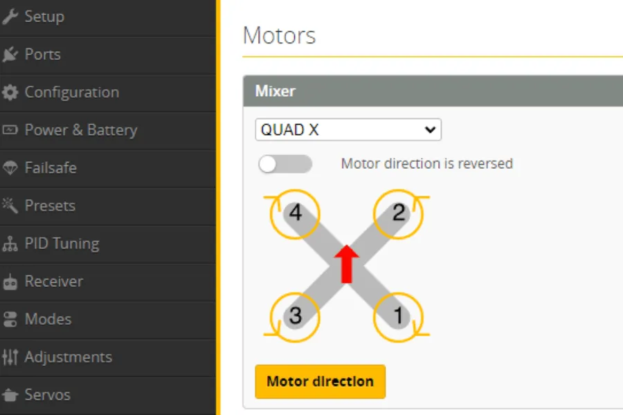
Motor order must match Betaflight’s layout:
- Motor 1 = Rear right
- Motor 2 = Front right
- Motor 3 = Rear left
- Motor 4 = Front left
Don’t worry about direction—reverse in BLHeli Configurator if needed.
Connecting 4 in 1 ESC to Flight Controller
How to Connect 4 in 1 ESC to Flight Controller? Firstly wiring esc to flight controller is important in order to accept inputs. There are several motor output connections on each flight controller; these are often identified by the labels motor1, motor2, and occasionally by S1, S2, or M1, M2, etc. You can locate these by consulting the flight controller manual or by looking for labels on your flight controller.
Each ESC requires two wires in order to be connected to your flight controller. A ground and a signal. While it’s not strictly required, using a ground wire is advised as best practice to guarantee that all electronic equipment have a common ground, so please connect it. It matters which ESC you link in what order. Your drone’s motor 1 and motor 2 must be connected to connections 1 and 2, respectively. The order you must utilize will be specified in the handbook that comes with your flight controller software.
For instance, you would connect this motor/ESC to the motor connection 1 on your flight controller since Betaflight requires the back right motor to be motor 1. Likewise, motor 4 (the front left motor) must be connected to your flight controller’s motor connector 4.
Let’s begin by examining the flight controller down below. It has ties with great labels. On the borders of the board, designated S1, S2, S3, and S4, are the four ESC connectors. Solder the signal wire from each of your ESCs to the appropriate pad. There is a ground pad next to each one, and you should solder the ESC signal ground wire to it.
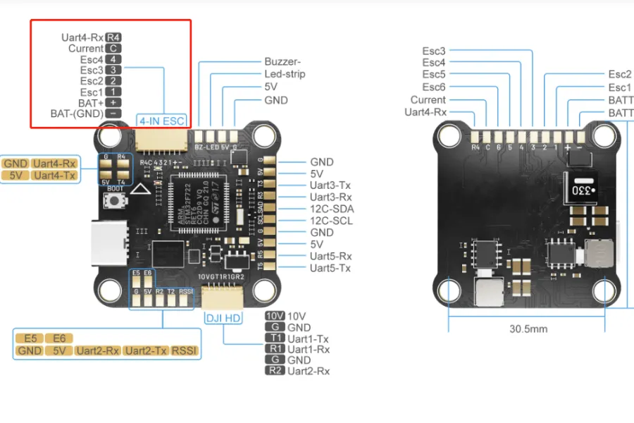
Power connections
The power connections are used to connect the ESC to the battery. The power wires are typically red for positive and black for negative.
ESC power pads → LiPo battery leads:
- Positive (red) → VBAT+
- Negative (black) → GND
Use appropriate wire gauge (12–14 AWG for 5” builds).
Add a low-ESR capacitor (1000µF 35V for 6S) across ESC power pads to filter voltage spikes.
Signal connections
The signal connections connect the ESC to the flight controller, and the signal wire is typically yellow.
Optional Connections
- Current Sensor (CUR): For current monitoring in Betaflight.
- Telemetry (TLM): UART feedback for RPM, temperature, voltage (optional if using bi-directional DShot).
- 5V / 10V Pads: Only needed if FC requires external regulator power.
Community Testing Opportunity
Connecting 4-in-1 ESCs to flight controllers varies by brand and pinout, and real-world reliability depends on more than just wiring diagrams. If you want to test different FC–ESC combinations, evaluate stability, or explore how various setups perform under flight load, consider joining the MEPSKING Vine Voice.
Pilots can receive free FPV components, conduct hands-on tests, and share honest feedback that helps the FPV community build safer and more reliable drones.

Configuration in Betaflight
System Configuration
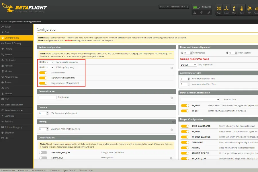
After configuring the receiver, we can now proceed to fine-tune a few Betaflight settings. We will first check the option for system configuration under the “Configuration Tab.”
You can choose your PID loop frequency and gyro update frequency here. For the majority of F7 flight controls, I advise configuring both to 8kHz.
In Configuration Tab:
- Check CPU load < 30%.
- Set Gyro/PID loop to 8kHz/8kHz (for F7 FCs).
You will need to save and restart your flight controller after completing this. To apply the gyro update, though, you must also physically unplug your flight controller. Then double check your CPU load along the bottom bar after you’ve connected back up. At this stage, you don’t want it to be running much higher than 20–30%.
Set Gyro/PID loop to 8kHz/8kHz (for F7 FCs).
ESC and Motor Configuration
Checking the settings on your motors and ESC is the next step. We must first inform Betaflight of the kind of ESC you are using by filling out the “ESC/Motors Feature” box on the “Configuration Tab.”
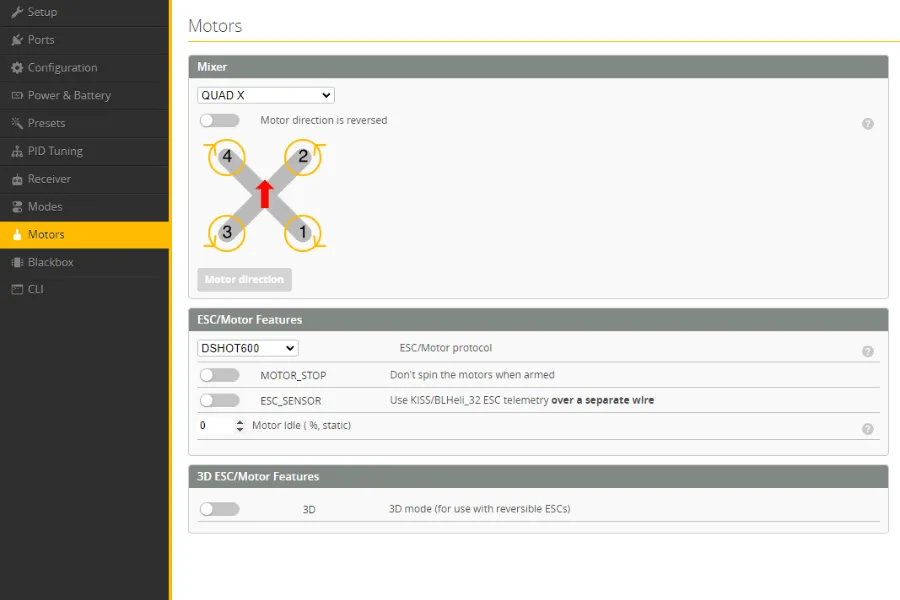
Here, you must indicate the protocol that your ESCs are operating on. Obviously, this may vary depending on the particular ESC you are using; for information on the protocol each ESC uses, see to its specifications. Oneshot, Multishot, Dshot, and Proshot are the options available to you. These days, almost all BLheli_S ESC operate on Dshot300. Thus if you’re unsure, I advise you to start with this setting. Choose Dshot600 if you are using a BLheli32 ESC.
Select correct ESC protocol:
- BLHeli_S → DShot300
- BLHeli_32 → DShot600
Test motors in Motors Tab:
- Confirm correct order and direction.
- Reverse spin if needed via BLHeli Configurator.
Current Sensor Calibration
- Enter scaling values in Power & Battery tab.
- Use a charger/wattmeter for accurate calibration.
Pro Tips from FPV Pilots
- Always use a smoke stopper when powering for the first time.
- Keep motor wires short to minimize electrical noise.
- Double-check solder joints under magnification before plugging in.
- Take photos before soldering—helps in troubleshooting later.
- Strain Relief: Leave a tiny bit of slack in the harness between the FC and ESC. If the frame flexes in a crash, you don’t want the wires pulling out of the connector.
FAQs
Why are my motors twitching but not spinning?
The short answer is usually a protocol mismatch or a loose signal wire. Ensure your ESC protocol in Betaflight (e.g., DShot600) matches what your ESC supports. Also, double-check that the ground (GND) wire in your harness is securely connected.
Can I connect any 4 in 1 ESC to any flight controller?
Yes, as long as the voltage and pinouts match. You can mix a MEPS ESC with a T-Motor FC, for example, but you must manually verify that the VBAT, GND, and Signal pins line up correctly in the wiring harness.
What happens if I connect the 4 in 1 ESC harness backward?
In most cases, you will fry the flight controller instantly. Because the harness carries full battery voltage (VBAT), plugging it into a 5V or Signal rail on the FC will cause permanent damage. Always “beep it out” with a multimeter first.
How do I know if my ESC is 4S or 6S compatible?
Check the rating of the capacitors and FETs on the board. Most modern 4 in 1 ESCs are rated for 3S-6S. Using a 4S-rated ESC on a 6S battery will result in the components exploding the moment you plug it in.
Conclusion
Wiring a 4-in-1 ESC to your flight controller is one of the most critical steps in FPV drone building. With proper wiring, capacitor filtering, and Betaflight configuration, you ensure smoother flights, accurate telemetry, and longer component life.
Community Testing Opportunity
Connecting 4-in-1 ESCs to flight controllers varies by brand and pinout, and real-world reliability depends on more than just wiring diagrams. If you want to test different FC–ESC combinations, evaluate stability, or explore how various setups perform under flight load, consider joining the MEPSKING Vine Voice.
Pilots can receive free FPV components, conduct hands-on tests, and share honest feedback that helps the FPV community build safer and more reliable drones.